Are you plagued by free particles in your hermetic packages causing intermittent shorts or damaging your sensitive electronics? Probably not. In large part this is due to the optimization of manufacturing processes to minimize the existence of these free particles.
Over the years, manufacturers have used Particle Impact Noise Detection (PIND: pronounced /Pē Ī ĭN Dē, Pĭn Dē, pĭnd/) to screen out particles in hermetic packages. In addition, PIND has helped manufacturers identify the particles and their origin so processes could be optimized to reduce the existence of damaging extraneous material.
Why PIND Testing?
While extraneous material has been reduced, the processes used to manufacture open cavity integrated circuits still have a probability of producing escapes. Materials found in packages include lid weld splatter, loose die-attach, pieces of die, loose bond wire material, and human contamination; just to name a few. In large part, this is why PIND is a standard screening step for Space grade parts. But what about non-space grade parts?
Non-Space grade parts are frequently used in high-reliability applications and damage caused by free particles is a very real concern. Because PIND screening is not included in the standard test flow many choose to perform screening on every lot purchased.
PIND Test Methods
The screening process for hybrids, multi-chip modules and monolithic microcircuits is defined in MIL-STD-883 Test Method 2020 and for transistors and diodes the requirements can be found in MIL-STD-750 Test Method 2052. Other device types may use alternate requirements and some customers choose to write their own requirements based on the construction of their particular device. For the purposes of this article we are going to focus on MIL-STD-883 TM 2020 and MIL-STD-750 TM 2052.
Over the years the test methods for PIND in MIL-STD-883 and MIL-STD-750 have been aligned with each other. There are a few areas where differences occur. First, the test frequency calculation is the same but the range is slightly different between the two specifications. The minimum frequency is the same for both but the maximum calculated frequency allowed for MIL-STD-750 is 130Hz and for MIL-STD-888 it is 150Hz. MIL-STD-750 states that if the frequency is less than 40 Hz then the test should be performed at 40 Hz. If the frequency is greater than 130 Hz then the test should be performed at 130 Hz. MIL-STD-883 states that if the calculated frequency is outside the range of 40Hz – 150Hz then an alternate frequency can be used if approved by the acquiring activity.
Both test methods provide two different conditions. Condition A is the most widely used and has a set acceleration during vibration of 20gs and frequency is the calculated value from the provided formula. Condition B has a set acceleration during vibration of 10gs and the frequency requirement is 60Hz minimum.
For condition B it is important to note that the frequency requirement provides a minimum but no maximum. In addition, there are no guidelines for setting the frequency to a different value. This gives the user the flexibility to determine the frequency of the test based on known limitations of their device. In addition, the lower acceleration allows more mechanically sensitive devices to be screened without the fear of mechanical damage that the test may induce.
For condition A the test frequency is set by the following formula published in both MIL-STD-883 TM 2020 and MIL-STD-750 TM 2052.
- Where: D = Average internal package height (in inches) as measured from the bottom of the lid to the top of the substrate or header.
- 20 is a constant in this application and is equal to sinusoidal acceleration of 20g.
- F is the test frequency in Hz
Now that we know our test frequency let’s step through the test process.
PIND Test Process
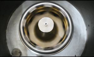
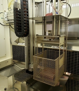
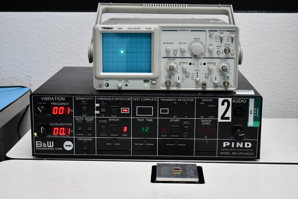
The first step in the screening process is the system checkout. There are two steps to this process. The first step is a test with a system sensitivity unit (STU) to ensure the test head will appropriately detect loose particle. The STU is mounted to the test head using the same acoustical coupling medium that will be used for screening and generates a pulse to mimic the event of a particle impacting the lid of a device. The second is a 30 to 60 second run of the shaker unit while monitoring the oscilloscope to ensure the noise level produced by the equipment is consistent and within a range that will not mask noise bursts. At Golden Altos we run a verification sample with a 1 mil particle based on the package type. When the system checks as complete, we are ready to test.
From a high level, the part is adhered to the test head using an acoustical coupling medium. Once securely mounted the part goes through four sequences of shocks and vibrations (as calculate) while the test technician monitors three different detection systems for noise bursts caused by loose particles. If a noise burst occurs the part fails and is segregated from the lot.
A sequence starts with three shock pulses followed by three seconds of vibration. This is repeated three more times to complete a run (4 total sequences makes up one run.) When the test run has been performed on all of the parts in the lot, determination will be made on lot disposition. The rules for dispositioning a lot in PIND are:
1. The run must have resulted in less than a 1% failure rate.
2. The total cumulative failure rate from all runs must be less than 25%.
3. If the run results in a higher failure rate than 1% but less than 25% all of the passing parts must be run again.
4. You can only run a lot five times. The lot will be failed any time the cumulative failure rate is greater than 25%.
5. Only five runs are allowed so regardless of the cumulative failure rate, if on the fifth run the individual run failure rate is greater than 1% then the lot fails.
Now let’s look at the parts of the test system.
First there is the test head. This includes the platen to mount the part on as well as a sensor to detect impact.
The amplifier increases the amplitude of the signal from the test head so it can be used to monitor noise bursts.
The shaker is where all the shock and vibrations of the parts is generated. The test head sits on top of the shaker.
The controller does just that, it controls the shaker and shock mechanisms to ensure frequency and acceleration of the vibration and shocks meet the required conditions.
There are three built in monitoring systems.
There is a threshold detector that monitors for noise bursts above the defined preset level and triggers a fail light if noise bursts occur.
There is an oscilloscope to visually monitor the vibration period for noise bursts above the system generated noise levels. It is important to note that a noise burst may not trigger the threshold detector but is still considered a failure if seen in this system.
Finally, there is an audio output that allows the test technician to monitor noise bursts based on the sound generated from a loose particle impacting the lid of the device.
Any one of these systems can be used to detect loose particles and detection of a particle by any one of these systems constitutes a failure.
PIND Testing with Golden Altos
If you are plagued by particles present in your packages or are just in need of screening to ensure all your parts are flight worthy, call Golden Altos and we will screen out suspect parts and eliminate any pesky particle problems.
Check out our video on Youtube showing the PIND test in action!