Our process is set up for each individual customer requirements for a reliable cut that will pass rigorous Military visual inspection criteria and can prevent failures from group testing due to stress that could be induced from device singulation. To enhance the quality and reliability of the dicing process, all wafers are processed with chilled deionized water, this will act both as a coolant and a lubricant. Chilled DI water can flush away the silicon particles generated by the dicing process. Surfactant injection into the DI water is also another option we employ to reduce the buildup and depositing of dicing debris on the exposed bonding pads. An Automatic Dispensing System, ADS2-LLC, is used for this procedure which has the ability to control the mix ratio of the surfactant. ESD protection is provided by a CO2 Inline Injector, ADT 947, which will maintain the resistivity between 0.5 to 1.0 MΩ/cm. This can effectively minimize electrostatic buildup during the dicing singulation process.
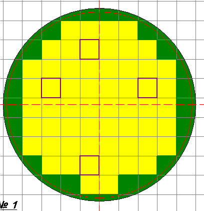
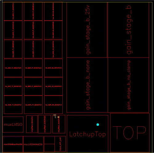
The presence of multiple die mask set in a single wafer is also not a hindrance. Depending on the layout such as multiple die within a reticle as seen in illustration #1 and #2 or difference die set for each quadrant.
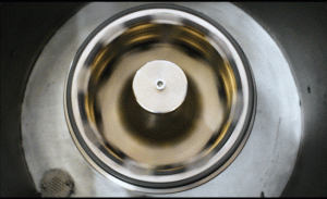
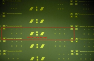
Difficult-to-cut wafer materials such as LiNbO3 have been processed for singulation at our facility. This requires proper selection of the blade material and optimization of the dicing process parameters. The lack of a clear saw street is not a hinderance for Golden Altos. Fiducials or reference points will be needed for this type of singulation. The photo to the right is an example of this type of singulation with a LiNbO3 wafer.
Golden Altos has the solution to extract the die with the highest possible yield. Uniform die within a quadrant is a simple process, this involves quartering the wafer to separate the different devices and dicing each quarter to the appropriate size. Different devices within the same reticle is similar to the process used for dicing different devices per quadrant. The wafer is first cut into the individual reticle and then each reticle will be mounted again on a separate wafer tape to be diced according to the most suitable cut pattern for maximum die yield. This may involve multiple wafer tape mounting of the reticle after each cut depending on the location of the saw streets.


